Corrosion challenges that offshore wind cannot ignore
Offshore wind structures see multiple corrosion mechanisms across zones, and each zone needs a different protection strategy to reach a 20–30 year service-life target with manageable maintenance.
Atmospheric exposure combines salt deposition, high humidity, and UV, while splash and tidal zones add repeated wetting, impact, and abrasion that accelerate breakdown once film integrity is compromised.
Zone-based challenges you should write into the spec
- Atmospheric zone: Salt-laden atmosphere plus UV and condensation cycles.
- Splash zone: Highest combined severity, wetting, drying, mechanical impact, and salt concentration.
- Tidal zone: Repeated immersion and exposure cycles that stress films and concentrate salts.
- Submerged zone: Continuous wet service where coating works together with cathodic protection.
Match ISO 12944 classification to offshore wind reality
Most offshore wind steel exposed above water is typically treated under severe marine atmospheric assumptions, often aligned with C5-M and CX logic, while offshore qualification and performance testing are addressed in ISO 12944-9 for offshore and related structures.
ISO 12944-9 explicitly targets offshore and related structures exposed to CX and immersion category Im4, and it lays out performance requirements and laboratory performance test methods for protective paint systems in these exposures.
For your project teams, the fastest way to align terminology and durability planning language is to link this classification back to your pillar page: ISO 12944 corrosion protection.
Coating requirements for offshore wind turbine towers
Wind turbine towers are large-area steel structures often coated in controlled shop conditions, then transported, assembled, and repaired at joints and handling points, so the system must be repairable and inspection-friendly.
A common tower direction uses a zinc-rich primer for corrosion control, a high-build epoxy for barrier build, and a polyurethane topcoat for weathering resistance and long-term appearance in exposed zones.
Typical system direction for tower external steel
- Primer: Zinc-rich epoxy primer direction for corrosion control at defects and edges.
- Intermediate: High-build epoxy direction for barrier build and thickness.
- Topcoat: UV-stable topcoat direction, often polyurethane for durable weathering.
Monopile and jacket foundation coating systems
Foundations drive the biggest lifecycle risk because access is difficult, splash zone severity is extreme, and repair cost is high offshore.
Monopiles typically need splash-zone strengthening, while jackets add complexity from weld density, bracing geometry, and higher stripe-coat demand on edges and connections.
Practical detail rule: on jackets, stripe coat and edge protection discipline often matters more than “average DFT on flats,” because failures start at geometry.
Splash zone coating systems, the most critical area
The splash zone is often the controlling zone for offshore wind durability planning because it combines mechanical impact, repeated wet-dry cycles, and high salt concentration.
ISO 12944-9 combines splash and tidal zones for qualification purposes into one set of tests, reinforcing that this zone needs a distinct performance mindset and not just “extra microns.”
Typical splash zone system direction
- Corrosion control base: Zinc-rich epoxy primer direction in high-risk areas.
- Specialty barrier intermediate: Glass flake reinforced epoxy direction to increase diffusion path length and barrier resistance.
- Additional barrier build: High-build epoxy layer direction to reach the target DFT ranges for the zone.
- Finish: Durable finish direction appropriate to exposure and maintenance plan, often polyurethane or fluorocarbon in fully exposed zones.
Internal tower protection systems that are often forgotten
Internal tower spaces can experience condensation, high humidity, and limited ventilation, which can create a persistent moisture environment even when the external steel is “only atmospheric.”
An internal epoxy system direction is commonly used for moisture tolerance and barrier protection, and the spec should define inspection access and repair rules because internal repairs are disruptive.
Cathodic protection vs coating: how they work together
On submerged steel, coatings and cathodic protection are designed to work together: the coating reduces current demand and protects the steel, while cathodic protection addresses defects and damage over time.
Engineering rule: do not “trade off” coating quality because CP exists, a weaker coating increases CP load and increases long-term risk and operating cost.
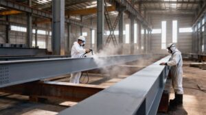
Surface preparation requirements for offshore wind
Surface preparation is where long-life offshore wind projects win or fail, and it must be written as an enforceable scope with verification, not a single line item.
Minimum controls to write into RFQs
- Sa 2.5 minimum for critical external steel, with defined profile range and acceptance method.
- Soluble salt testing plan and acceptance criteria, because residual salts can drive blistering and early breakdown in marine exposure.
- Weld inspection and defect correction before coating, because weld geometry drives stripe-coat demand and early failures.
- Edge rounding requirement and stripe coats on edges and welds, then verify DFT at details, not only on flats.
- Dew point discipline and climate logging during coating, because condensation is a common offshore rework trigger.
If your inspection teams need a ready hold-point structure, reference: Steel Structure Coating Inspection Checklist.
Typical design life for offshore wind coating systems
Offshore wind design often targets 20 years, 25 years, or 30 years, and reaching higher bands usually means higher barrier build, tighter detail control, and stronger execution discipline, not just a different brand.
When you move from a 20-year mindset to 25+ years, the splash zone typically becomes the controlling specification zone, which is why system architecture and qualification focus there.
Common coating failures in offshore wind projects
- Edge corrosion and weld-line breakdown due to insufficient stripe coats and low DFT at details.
- Splash zone early failure when a general atmospheric system is used without the right barrier architecture.
- Cracking or delamination caused by poor surface preparation, contamination, or intercoat timing issues.
- Installation and transport damage not covered by a defined repair scope, leading to weak “as-installed” protection.
Cost considerations for offshore wind coating systems
High-build and splash-zone-strengthened systems increase initial cost, but offshore rework cost is disproportionately high because access, safety controls, and downtime dominate the spend.
Procurement rule: saving a small percentage in initial coating scope can multiply lifecycle cost if it increases repaint cycles or offshore repair interventions.
For heavy-duty corrosion environments used as budgeting baselines, reference: Heavy Duty Anti-Corrosion Coatings for Industrial Projects.
Step-by-step: select the right offshore wind turbine coating system
- Identify structure type and zones, tower, transition piece, monopile, jacket, splash and tidal zone, submerged zone, and internal tower environment.
- Assign classification logic for severe marine atmospheric exposure and offshore performance expectations using ISO 12944 concepts, and reference offshore qualification requirements when relevant.
- Set the design life band and maintenance window, then choose a system architecture per zone.
- Define DFT ranges by layer and by detail and require stripe coats at edges and welds.
- Align coating and cathodic protection strategy for submerged zones.
- Build the QC dossier and hold points into the RFQ so bids are comparable.
Engineering recommendations for 25+ year offshore wind projects
- Strengthen the splash and tidal zone with a dedicated barrier architecture rather than “thicker tower paint.”
- Increase stripe-coat discipline and inspection density at edges, welds, and repairs.
- Enforce salt control and climate logging as acceptance deliverables, not optional “good practice.”
- Define transport and installation damage repair rules so the as-installed system matches the as-specified system.
RFQ checklist
- Project location and distance to coast, plus expected salinity and temperature bands.
- Structure type and steel scope, tower, monopile, jacket, transition piece; estimated area and geometry complexity.
- Zone map, atmospheric, splash and tidal, submerged, internal.
- Design life target, 20 years, 25 years, or 30 years, and planned inspection frequency.
- Surface preparation capability, containment, blasting feasibility, salt testing plan, and profile verification.
- QC dossier, DFT readings by layer, climate logs, repair method and records, handover documentation.
- Cathodic protection approach for submerged zones and interface responsibilities.
CTA
Contact us for customized offshore wind turbine coating system design based on project location, structure type, and required service life, and request TDS plus a system recommendation via Contact Industrial Coating Manufacturer.