Here’s a question we get from engineers and project managers fairly often: how thick does the intumescent coating actually need to be?
It sounds like it should have a simple answer. It doesn’t — at least not without knowing a few things about the steel section you’re protecting. The required dry film thickness (DFT) varies considerably from one member to another, even on the same structure. A light UB section might need 3 mm of intumescent. A heavy UC column on the same project might only need 1.2 mm. Get this wrong in either direction and you’ve got a problem — under-application means the steel isn’t protected; over-application wastes material and, in some systems, can actually crack on the first thermal cycle.
This guide walks through the calculation step by step. No shortcuts — just the actual method.
The Core Variable: Section Factor (Hp/A)
Everything in intumescent coating thickness calculation starts with the section factor, written as Hp/A (sometimes called the profile factor).
Hp is the heated perimeter of the steel section — the length of the section’s outline that is exposed to fire. A is the cross-sectional area of the steel. So Hp/A is essentially a measure of how much surface area is exposed to heat relative to the steel’s mass.
A high Hp/A value means a lightweight section with a lot of exposed surface relative to its volume — it heats up fast, so it needs more coating. A low Hp/A means a heavy, compact section — it takes longer to heat through, so less coating is needed. That’s the intuition.
The units are m⁻¹. Typical values in structural steelwork range from around 50 m⁻¹ for a very heavy column section up to 350 m⁻¹ or more for a light beam or hollow section.
How to Calculate Hp/A
For a standard open section (I-beam, H-column) exposed to fire on three or four sides, the heated perimeter is just the sum of the exposed face lengths. The cross-sectional area is taken from the steel section tables.
For a 254x254x89 UC exposed on four sides, for example: you’d take the perimeter from the section tables and divide by the cross-sectional area. The SCI (Steel Construction Institute) publishes Hp/A values for standard UK and European sections, and most major steel design software will calculate it automatically. If you’re working from first principles — don’t. Use the manufacturer’s section factor tables or the SCI data. Manual calculation errors here cascade through the whole DFT specification.
One thing worth knowing: if the steel is boxed in (enclosed in a suspended ceiling, for example, with fire only able to reach it from one side), the heated perimeter changes. Hp/A drops. Which means the required coating thickness drops too. Always confirm the exposure condition before running the numbers.
The Other Three Variables You Need
Section factor alone doesn’t give you a DFT. You also need:
1. The Required Fire Resistance Period
This comes from the structural fire engineering report or the building regulations — not from the coating manufacturer, and not from guesswork. Common ratings are 30, 60, 90, and 120 minutes. Occasionally 180 minutes for highly critical structures.
The longer the required period, the thicker the coating needs to be. Roughly speaking, going from 60 to 90 minutes might add 30–50% to the required DFT depending on the section. Going to 120 minutes can more than double it on light sections.
2. The Fire Curve
There are two main scenarios: cellulosic (the standard building fire curve, referenced in BS 476 Part 20/21 and EN 13501-2) and hydrocarbon (the fast-rise UL 1709 curve used in petrochemical and offshore applications). These are not interchangeable. A product tested only to BS 476 is not validated for UL 1709 service. In practice, if you’re specifying for a refinery, an LNG facility, or anything offshore, you need UL 1709-tested data.
For more on the difference between these two standards, see our Fireproof Coating Standards: UL 1709 vs BS 476 Explained comparison guide.
3. The Critical Steel Temperature
This is the temperature at which the steel section loses enough strength to fail under its design load. For standard structural steel under normal loading, this is typically 550°C. But for heavily loaded sections — or sections with a high utilisation ratio — the critical temperature can be lower. 500°C is not unusual. If the critical temperature is lower, the coating has to work harder to keep the steel below it, which generally means more thickness.
The critical temperature is calculated by a structural engineer, not picked from a table. If you don’t have it, use 550°C as a conservative default — but flag this assumption in the specification.
Using the Manufacturer’s DFT Tables
Once you have Hp/A, the fire resistance period, the fire curve, and the critical temperature, you look up the required DFT in the coating manufacturer’s certified data tables.
These tables are product-specific. They’re derived from fire tests conducted by an accredited laboratory (Warrington Fire, Exova, Efectis — that kind of place). The test certificates are issued for a specific product, at a specific DFT range, on specific section factors, for a specific fire resistance period. You cannot mix and match data from different manufacturers’ tables.
The lookup works like this: find your section factor row, find your fire resistance period column, and read off the required DFT. Simple enough — but there’s a catch. Most tables are built for a critical temperature of 550°C. If your critical temperature is different, the manufacturer needs to provide corrected data, or the structural engineer needs to apply correction factors from the relevant code (EN 1993-1-2 / BS 5950-8 are the usual references). Don’t just use the standard table without checking the critical temperature assumption.
Example Calculation
Let’s say you have a 356x171x51 UB (universal beam), exposed on three sides (bottom flange in contact with a concrete slab), with:
- Hp/A = 210 m⁻¹ (three-sided exposure, from section tables)
- Required fire resistance: 90 minutes
- Fire curve: cellulosic (BS 476 / EN 13501)
- Critical temperature: 550°C
You look up 210 m⁻¹ / 90 min in the manufacturer’s table for their intumescent product. The table gives — let’s say — 2.4 mm DFT minimum. That’s your target. In practice, you’d specify 2.4 mm minimum with a 10% tolerance band, and inspection would confirm no single reading falls below 2.16 mm (90% of minimum).
If the same beam were a 610x229x125 UB — a much heavier section — Hp/A might be only 130 m⁻¹. The same 90-minute cellulosic requirement might only need 1.5 mm. Same fire rating, same beam length visually, but nearly 40% less coating.
💡 This is exactly why applying a single DFT across an entire project is wrong. Different sections genuinely need different thicknesses, and over-specifying on heavy sections wastes material while under-specifying on light sections is a code violation.
Indicative DFT Ranges by Section Factor and Rating
The numbers below are illustrative — based on typical thin-film intumescent systems for cellulosic fire exposure at 550°C critical temperature. Do not use these for specification. Always refer to the specific product’s certified test data.
| Section Factor Hp/A (m⁻¹) | 60 min (cellulosic) | 90 min (cellulosic) | 120 min (cellulosic) |
| ≤ 100 (heavy sections) | 0.5–0.9 mm | 0.8–1.4 mm | 1.2–2.0 mm |
| 100–150 | 0.8–1.4 mm | 1.2–2.2 mm | 1.8–3.0 mm |
| 150–200 | 1.2–2.0 mm | 1.8–3.0 mm | 2.5–4.0 mm |
| 200–250 | 1.6–2.6 mm | 2.4–3.8 mm | 3.2–5.0 mm |
| 250–300 (light sections) | 2.0–3.2 mm | 3.0–4.8 mm | 4.0–6.0 mm+ |
For UL 1709 hydrocarbon fire scenarios, required DFT is typically 20–40% higher than cellulosic for equivalent section factors and fire periods — because the hydrocarbon curve reaches 1,093°C within five minutes, compared to the slower rise of the cellulosic curve.
Application Tolerance and Inspection
Calculating the DFT is one thing. Making sure the applied coating actually hits it is another.
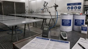
Thin-film intumescent is applied wet, and the wet-to-dry ratio matters. Most systems have a volume solids content of 65–80%, meaning the wet film needs to be applied at roughly 1.3–1.5 times the target DFT to achieve the right thickness once cured. Wet film thickness (WFT) gauges are used during application; dry film thickness gauges (magnetic induction, calibrated to the steel substrate) confirm the cured result.
The standard inspection protocol in most UK and European projects follows BS EN ISO 19840 — which sets out measurement frequency, acceptance criteria, and what to do with readings that fall below the specified minimum. The basic rule: if less than 20% of readings are below minimum, top-up application is required on those areas. If more than 20% are below minimum, you’ve got a bigger problem and the specification needs re-examining.
One practical issue that comes up often: intumescent is hard to apply evenly on complex geometry. Beam/column connections, bolted end plates, web stiffeners — these are the areas most likely to have thin spots. Stripe coating (a brush-applied coat specifically targeting edges and connections before the main spray coat) is usually specified for exactly this reason.
Common Mistakes Worth Knowing About
A few things we see go wrong repeatedly in intumescent specification and application:
Using a single DFT for the whole project. It’s administratively convenient but technically wrong. A blanket DFT either over-specifies heavy sections (wasting material and money) or under-specifies light ones (code non-compliance). The right approach is a section-by-section DFT schedule.
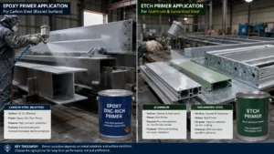
Ignoring the primer system. Intumescent coatings are tested and certified as a complete system — primer, intumescent, topcoat. Swap the primer for a cheaper alternative and you’ve broken the certification. The test certificate becomes invalid. This is surprisingly common on cost-squeezed projects.
Applying too thick. This one surprises people. Most thin-film intumescent systems have a maximum single-coat DFT. Exceeding it — particularly in corners and recesses where coating tends to pool — can cause mud-cracking on the first thermal cycle. The coating still expands, but the cracked film loses some of its insulating efficiency.
Not checking the overcoat window. If the intumescent is left too long before topcoating (or before the next coat of intumescent), the surface can become too hard to bond to. The manufacturer’s technical data sheet gives the overcoat window — it’s usually defined in hours at a given temperature, and it narrows considerably in hot weather.
A Few Questions We Get Asked
Can I use one manufacturer’s DFT table with another manufacturer’s product?
No. Fire test data is product-specific. A table produced from tests on Product A is not valid for Product B — even if they look similar, even if they’re both ‘thin-film intumescent’, even if they’re from the same chemical family. If you’re switching manufacturers mid-project, you need new certified data for the new product at the same section factors and fire resistance periods.
What if my section factor falls between two values in the table?
Interpolation is generally acceptable — most certification bodies allow linear interpolation between adjacent data points in a test table. But check the specific product certificate and the applicable code (EN 13381-8 or SCI P160 in the UK context). Some certifications explicitly allow interpolation; some require you to use the next more conservative value. When in doubt, use the conservative value and document the assumption.
How does a topcoat affect the intumescent performance?
The topcoat is part of the certified system — but it mainly affects corrosion protection and aesthetics, not fire performance, as long as it’s within the specified DFT range. Applying a topcoat that’s too thick can theoretically impede the intumescent expansion slightly, which is why most certifications cap the topcoat DFT. Typically 80–100 µm polyurethane is the limit. Check the specific certificate.
Do hollow sections (CHS/RHS) need different calculations?
Yes — and they’re worth flagging specifically. Hollow sections have no access to the interior for fire protection, so the fire exposure is external only. But the heated perimeter calculation changes depending on whether the ends are sealed or open. Additionally, some intumescent products are specifically certified for hollow sections while others are not — the expansion behaviour of the char inside the hollow profile is different from an open section. Always confirm hollow section certification with the manufacturer before specifying.
Need a DFT Specification for Your Project?
Send us your steel schedule — section sizes, exposure conditions, required fire resistance period, and applicable fire curve — and we’ll prepare a project-specific DFT specification at no charge. We manufacture intumescent systems rated to 60, 90, and 120 minutes under both BS 476 Part 21 and UL 1709, with full third-party fire test certificates.
Related reading that might be useful:
- Fireproof coating thickness guide (broader overview): Fireproof Coating Thickness Guide for Steel Structures.
- Intumescent coating for steel — full guide: Intumescent Fireproof Coating for Steel: 60/90/120 Min Rating Guide.
- UL 1709 vs BS 476 — which standard applies to your project: Fireproof Coating Standards: UL 1709 vs BS 476 Explained.
- Passive vs active fire protection — understanding the system: Passive Fire Protection vs Active Fire Protection.
Send your steel schedule and project details via the project inquiry form and our technical team will respond with a section-specific DFT specification.