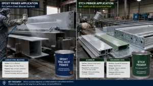
Applying epoxy coating to flat steel plate and applying it to fabricated structural sections — I-beams, H-columns, hollow sections, angles, channels — are different propositions. The product is the same. The surface preparation is the same. But the geometry creates specific challenges that flat-surface coating experience doesn’t fully prepare you for.
Edges corrode first. Weld toes are the most vulnerable points. The re-entrant corners of flanges and webs create spots where blasting can’t reach easily and where coating tends to pull thin during cure. Understanding these specifics — and specifying for them — is the difference between a coating system that performs as designed and one that starts showing rust at weld lines within a few years.
Why Structural Section Geometry Creates Coating Problems
Three geometric factors create coating challenges that don’t exist on flat surfaces:
Edge thinning. Coating films thin at sharp edges due to surface tension effects — the liquid coating pulls back from edges as it levels, leaving a thinner film than on adjacent flat surfaces. The sharper the edge, the more pronounced the effect. On a rolled steel flange edge (radius typically 2–5mm), coating applied at 150 µm target DFT may cure to only 60–80 µm at the edge itself. This is where corrosion initiates.
Weld geometry. Weld toes — the intersection of the weld bead with the base metal — are points of stress concentration and, frequently, of coating thinness. The weld profile creates a concave angle that is difficult to blast effectively and where airless spray tends to apply uneven coverage.
Re-entrant corners and web-flange junctions. The interior corners of I-sections and H-columns are difficult to blast to Sa 2.5 with standard equipment and difficult to coat uniformly with airless spray. These areas often receive less abrasive impact during blasting (leaving more residual mill scale) and less coating during spray application.
Stripe Coating: The Essential First Step
Stripe coating is a brush-applied coat applied specifically to edges, welds, bolt holes, and re-entrant corners before the main spray coat. Its purpose is to build up coating thickness at these geometrically vulnerable areas to at least the specified minimum DFT. Stripe coating is not optional on structural steel — it is a standard requirement in virtually all industrial coating specifications and should be specifically included in yours.
The stripe coat is typically applied after the primer has cured and before the intermediate coat is sprayed. It uses the same product as the coat it precedes (intermediate coat stripe before spray intermediate; topcoat stripe before spray topcoat) to avoid compatibility issues. Application by brush ensures the coating is worked into re-entrant corners and properly wets weld toes.
What to include in the stripe coat requirement:
- All exposed edges of flanges, webs, plates, and gussets
- All weld seams and weld toes
- Bolt holes — both the hole face and the area immediately surrounding the hole
- Bolted connection zones — particularly bolt heads and nut faces
- Any area of pitting or surface irregularity
The stripe coat typically adds 50–100 µm additional DFT at these locations, bringing them into compliance with the specified minimum. The structural steel coating specification guide covers how stripe coat requirements fit into a complete hold-point specification.
DFT Specification by Section Type
The section factor (Hp/A — heated perimeter to area ratio) that determines intumescent coating thickness has a parallel relevance in anti-corrosion specification: lighter, thinner sections have more exposed surface area relative to their mass, which means corrosion attacks a larger fraction of the material. DFT targets for light sections should be at the upper end of the specified range, and inspection of light sections should be more thorough.
| Section Type | Typical Application Challenge | Specification Note |
|---|---|---|
| Universal Beam (UB) / I-section | Edge thinning on flange tips; web-flange junction corners | Stripe coat all flange edges and web-flange junctions; verify DFT at flange tips specifically |
| Universal Column (UC) / H-section | Similar to UB but more compact; bolt connection areas | Stripe coat connection bolt areas; verify DFT on all four flange edges |
| Circular Hollow Section (CHS) | Curved surface — more uniform DFT, but weld areas are critical | Verify DFT at welds; check for sagging at underside in horizontal spans |
| Rectangular Hollow Section (RHS) | Four sharp corners with significant edge thinning | Stripe coat all four corners; RHS often has more pronounced edge thinning than open sections |
| Angle sections | Two edges meeting at the corner — both vulnerable | Corner stripe coat critical; easy to miss internal corner of angle in spray application |
| Channel sections | Open re-entrant on web-flange junction | Internal channel face is difficult to spray; brush application or stripe coat required |
Surface Preparation on Complex Geometry
Standard airless abrasive blasting works well on flat and moderately complex surfaces. On structural sections with tight re-entrant corners and complex geometry, blind spots in blast coverage are common. Before coating, inspect specifically for:
- Residual mill scale in web-flange junctions — the abrasive stream doesn’t hit this area at the right angle to clean it effectively with a single blast pass
- Inadequate profile in corners — measure surface profile with Testex tape in the flat areas and visually verify in corners
- Weld spatter — must be removed before blasting, not after; spatter creates sharp protrusions that shadow the surrounding steel from the abrasive
For tight corners and re-entrant geometries, supplementary mechanical preparation (needle gun, angle grinder, flap disc) may be necessary to achieve ISO 8501-1 Sa 2.5 in areas that abrasive blast can’t effectively reach. Specify this in the application procedure for complex geometry steel. The steel structure coating inspection checklist covers hold-point verification at surface prep, including inspection of complex geometry blind spots.
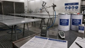
Application Equipment for Structural Sections
Airless spray is the standard application method for industrial coating on structural steel. For structural sections, tip selection matters:
- Fan width: a narrower fan (40–50°) is more controllable in tight areas; a wide fan (65–80°) covers flat surfaces faster but creates overspray in confined areas
- Gun positioning: maintain 30–50cm from the surface; keep the gun perpendicular to the surface being coated. Angling the gun to reach re-entrant corners reduces DFT on those surfaces
- Multi-pass technique: for flanges, coat the top face, then the underside, then the edges — as separate passes rather than trying to cover all surfaces in one pass
Frequently Asked Questions
Do I need to specify a minimum edge radius for structural steel to improve coating performance?
Yes — this is worth specifying, particularly for fabricated steel where sharp cut edges are common. A minimum radius of 2mm on all exposed edges is a standard requirement in demanding coating specifications (ISO 12944-5 references this as a surface quality requirement). Grinding or chamfering cut edges to this radius significantly reduces edge thinning and is a one-time cost at fabrication stage that prevents ongoing coating maintenance cost — far cheaper than recoating prematurely failed edges after erection.
Can I use brush application for the full coating system on structural steel, not just stripe coat?
Technically yes — most epoxy and polyurethane systems can be brush-applied. In practice, achieving consistent DFT by brush over large areas is difficult, production rates are much lower, and film quality (uniformity, absence of brush marks) is inferior to airless spray. Brush application is appropriate for stripe coats, touch-up of small areas, and situations where spray application isn’t practical (confined spaces, areas near sensitive equipment). For structural steel coating on any significant area, specify airless spray as the primary application method.
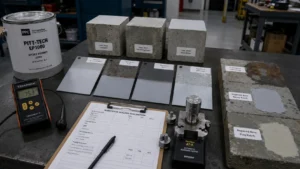
How do I measure DFT at flange edges and weld toes?
Use a calibrated magnetic induction DFT gauge following SSPC-PA 2 or ISO 19840. On narrow flange edges, position the gauge probe flat against the edge face — some gauges struggle with curvature and narrow contact areas, so confirm your gauge type is suitable. At weld toes and corners, take readings immediately adjacent to the weld rather than on the weld bead itself (the weld profile affects gauge accuracy). Record edge readings separately from flat surface readings — they should meet the same minimum DFT, but low readings at edges are the most common reason for coating specification non-compliance.
What happens at bolted connection areas — do they need a different coating approach?
Bolted connections require careful specification of two things: the coating applied before assembly (to the faying surfaces and bolt holes), and the coating applied after erection (to bolt heads, nuts, and exposed connection steel). Slip-critical connections may require restrictions on coating thickness at faying surfaces — check the structural engineer’s requirements before specifying. For non-slip-critical connections, coat the faying surfaces with primer only (no intermediate or topcoat) before assembly, then stripe coat and topcoat the assembled connection on site. Bolt heads and nut faces are particularly vulnerable to corrosion and must be included in the stripe coat requirement.
Is epoxy coating suitable for steel columns in contact with concrete at column bases?
The interface between a steel column and a concrete base — the grout pad or base plate zone — is a specific corrosion risk: moisture collects, remains for extended periods, and the alkaline concrete environment can interact with some coating systems. For this zone, extend the coating system 150–200mm below the top of concrete level using an immersion-rated epoxy or coal tar epoxy product, not the standard atmospheric epoxy. The base of the column — including the grout pocket if accessible — should receive at least Sa 2.5 preparation and a heavy-build coating. This zone is frequently missed in standard coating specifications.
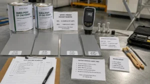
Epoxy Coating Systems for Structural Steel from Huili Coating
Huili Coating manufactures two-component epoxy coating systems for structural steel sections — zinc-rich primers, high-build epoxy intermediates, and polyurethane topcoats — with application procedures that specifically address complex geometry requirements including stripe coat specification and DFT inspection at edges and welds.
To recommend the right system and provide TDS or application procedure documentation, send your project details via the Huili Coating project inquiry form:
- Structural steel section types (UB, UC, CHS, RHS, angles, channels — or mixed)
- Environment category (ISO 12944 C3, C4, or C5 — or site description)
- Application stage: shop-applied primer and intermediate, site topcoat, or full site application
- Any special zones: column bases in contact with concrete, high-temperature sections, bolted connections with slip-critical requirements
- Required durability range and design life
- Surface preparation method available (shop blast, site blast, supplementary mechanical prep)
The technical team will provide a coat-by-coat system recommendation including specific stripe coat product, application procedure for complex geometry, DFT inspection guidance, and full product documentation.